
The following case study documents the completion of a pipe ramming job in Shercock, Co. Cavan. The works commenced on July 9th 2013 and were completed on the same day.
Scope of the works:
The works consisted of the installation of a steel casing drainage pipe underneath a country road in order to connect the drainage systems between two paddocks. Pipe ramming was chosen as the preferred methodology.
Methodology:
Pipe Ramming is a trenchless method for the installation of steel pipes and casings. Typically, distances of up to 30m long and up to 1500mm Diameter are feasible. This method is usually employed for shallow installations under railway lines and roads. The method delivers pneumatic percussive blows to drive the pipe through the ground. The leading edge of the pipe is typically left open. This directs the soil into the interior of the pipe instead of compacting it outside the pipe. Once the installation is complete, the spoil is typically removed using an auger, compressed air or water jetting.

Figure 1 shows the steel pipe that is to be rammed through the ground beneath the road.
Specs:
11m in length.
500mm Internal Diameter.
523mm External Diameter.

Figure 2 shows the completed trench cut out. The lower trench in the middle is for the placement of the pipe, while the outer trench is for the digger’s access. The road we are ramming beneath is just beyond the shrubbery in the background of the picture.
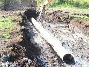
Figure 3 shows the pipe being hoisted into position into the lower trench. Levels are monitored at this point and for the remainder or the ramming to ensure the correct incline (1%) is achieved. It is monitored using a total station and level.
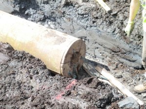
Figure 4 shows the collets after being inserted into the end of the pipe to be rammed. The purpose of the collets is to securely lock the pipe rammer to the casing during ramming.
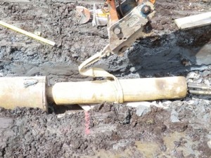
Figure 5 shows the pneumatic pipe rammer securely locked to the collets ready to begin ramming.
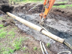
Figure 6 – With the both the steel casing pipe and the pipe rammer in place, ramming can begin.
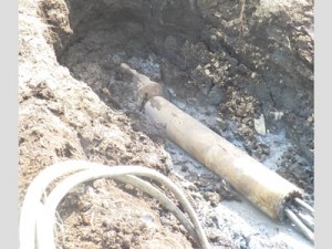
Figure 7 shows the completion of the pipe ramming. At this stage the pipe had been received at the opposite end.
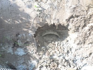
Figure 8 shows the rammed pipe protruding out of the soil as it has reached the far end. The spoil will be removed from the pipe using either an auger, compressed air or water jetting.
Some other examples of Pipe Ramming:
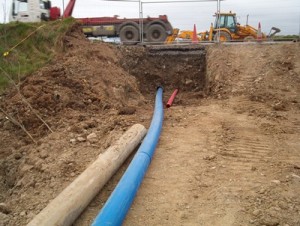
Figure 9 shows another completed pipe ramming job. Here, there were 2 pipes being rammed, one for a water pipe and the other for electric cables.
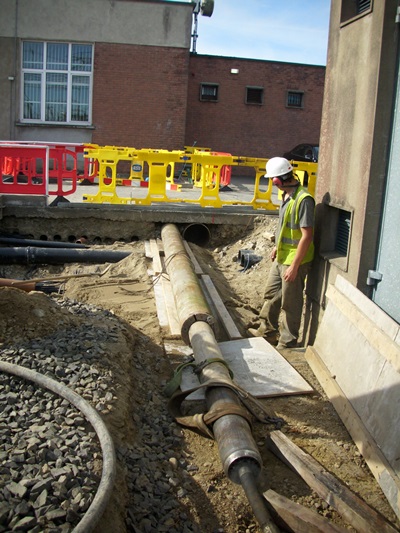
Figure 10a documents a pipe ramming job being completed at an ESB plant in Baltray, Co Louth.

Figure 10b documents the same job as in Figure 10a from a different angle.